![]()
![]()
Next: Design of Mercy
Up:
Mercy: a fast large Previous: Mercy design goals
Subsections
Since most of Mercy's operations are based around 32-bit
words, we define ![]() . Vectors are
indexed from zero, so a vector
. Vectors are
indexed from zero, so a vector ![]() of 128 32-bit
numbers will be indexed as
of 128 32-bit
numbers will be indexed as ![]() . The
symbol
. The
symbol ![]() represents bitwise
exclusive OR; where
represents bitwise
exclusive OR; where ![]() appears in the
figures with a square box around it, it represents addition in
the ring
appears in the
figures with a square box around it, it represents addition in
the ring ![]() . Least significant and lowest
indexed bytes and words appear leftmost and uppermost in the
figures.
. Least significant and lowest
indexed bytes and words appear leftmost and uppermost in the
figures.
Note that some details that would be needed to build a specification of Mercy-based file encryption sufficient for interoperability, such as byte ordering within words, are omitted since they are irrelevant for cryptanalytic purposes.
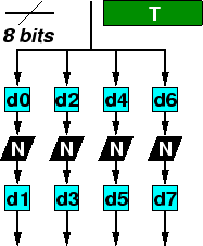
The ![]() box (
box ( ![]() , Figure
1) is a
key-dependent mapping of bytes onto words.
, Figure
1) is a
key-dependent mapping of bytes onto words. ![]() represents multiplicative inverses in
represents multiplicative inverses in ![]() with polynomial base
with polynomial base
![]() except that
except that
![]() .
. ![]() are key
dependent bijective affine mappings on
are key
dependent bijective affine mappings on ![]() .
.
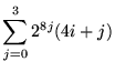
![$\displaystyle T(x)=\sum ^{3}_{i=0}2^{8i}d_{2i+1}[N(d_{2i}[x])]$](img31.png)
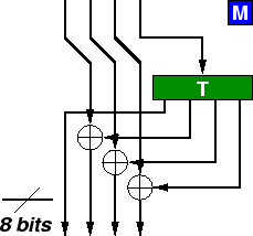
![]() (Figure
2) is drawn
from David Wheeler's stream cipher WAKE [21]; it's a simple,
key-dependent mapping on 32-bit words. The most significant
byte of the input word is looked up in the
(Figure
2) is drawn
from David Wheeler's stream cipher WAKE [21]; it's a simple,
key-dependent mapping on 32-bit words. The most significant
byte of the input word is looked up in the ![]() box, and the output XORred with the other three
bytes shifted up eight bits; the construction of the
box, and the output XORred with the other three
bytes shifted up eight bits; the construction of the ![]() box ensures that this mapping is
bijective.
box ensures that this mapping is
bijective.
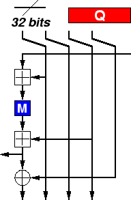
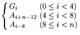
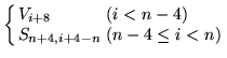
The ![]() state machine (Figure 3) maps a
four-word initial state and one word input onto a four-word
final state and one word output (
state machine (Figure 3) maps a
four-word initial state and one word input onto a four-word
final state and one word output ( ![]() ) using taps from a linear feedback shift register and a
nonlinear mixing function.
) using taps from a linear feedback shift register and a
nonlinear mixing function.
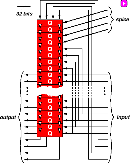
The ![]() function (
function (![]() ; Figure 4) accepts a
128-bit spice
; Figure 4) accepts a
128-bit spice ![]() and a
and a ![]() -bit input
-bit input ![]() and generates a
and generates a
![]() -bit output
-bit output ![]() (
( ![]() ).
). ![]() (usually just
(usually just ![]() ) is the F function for the
Feistel rounds. Here
) is the F function for the
Feistel rounds. Here ![]() represents
successive 128-bit states of a state machine;
represents
successive 128-bit states of a state machine; ![]() are the
successive 32-bit inputs to the state machine, and
are the
successive 32-bit inputs to the state machine, and ![]() are the
outputs.
are the
outputs.
|
|
|
|
|
|
|
|
|
|
|
|
|
|
|
|
|
|
|
|
|
|
|
|
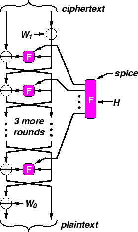
Mercy uses a six round Feistel structure (Figure 5) with partial
pre- and post-whitening; unusually, the final swap is
not omitted. The spice ![]() (usually the sector
number) goes through a ``spice scheduling'' procedure,
analogous with key scheduling, through which the ``spice
material''
(usually the sector
number) goes through a ``spice scheduling'' procedure,
analogous with key scheduling, through which the ``spice
material'' ![]() is generated
based on the input spice, using the
is generated
based on the input spice, using the ![]() variant of the
variant of the ![]() function; this forms
six 128-bit ``round spices''. Spice scheduling uses a dummy
input to the F function; for this a vector of incrementing
bytes
function; this forms
six 128-bit ``round spices''. Spice scheduling uses a dummy
input to the F function; for this a vector of incrementing
bytes ![]() is used.
is used. ![]() represents the
plaintext,
represents the
plaintext, ![]() the ciphertext,
and
the ciphertext,
and ![]() the
whitening values. We describe decryption below; since Mercy is
a straightforward Feistel cipher encryption follows in the
straightforward way.
the
whitening values. We describe decryption below; since Mercy is
a straightforward Feistel cipher encryption follows in the
straightforward way.
|
|
|
|
|
|
|
|
|
|
|
|
|
|
|
|
|
|
|
|
|
|
|
|
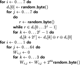
The key is used to seed a CPRNG from which key material is
drawn; [10] is used in the
sample implementation (after discarding 256 bytes of output),
and is convenient since it's small and byte oriented, but any
strong CPRNG will serve. Then the procedure in Figure 6 generates
the substitutions ![]() and the 2048-bit
whitening values
and the 2048-bit
whitening values ![]() .
.
An expected 10.6 random bytes will be drawn for each ![]() . Once
. Once ![]() have been
determined, a 1k table representing the
have been
determined, a 1k table representing the ![]() box can be generated. During normal use 1536
bytes of key-dependent tables are used.
box can be generated. During normal use 1536
bytes of key-dependent tables are used.
![]()
![]()
Next: Design of Mercy
Up:
Mercy: a fast large Previous: Mercy design goals